 |
DESIGNED & OPTIMISED EXCLUSIVELY FOR
FOURIER TRANSFORM
RAMAN SPECTROMETERS |
|
SEALED SOLID HOT CELL (H4)
OPERATING INSTRUCTIONS
UNPACKING THE CELL
The H4 cell is supplied fully assembled except that the 1/16"
stainless steel capillary tube is NOT fitted. You will find several tools and spares
including:
| ITEM |
QUANTITY |
| Pressure pad |
1 |
| Tool O ring removal |
1 |
| 4" adjustable spanner |
1 |
| Hexagon screwdriver 2mm A/F |
1 |
| Spare O rings and screws |
Bag |
| Spare window |
1 |
| Conventional hot cell accessory |
1 |
PRINCIPLES OF OPERATION
The H4 cell system comprises an oven fitted with window carrier and
window at the front and a sealing system at the back. The sample is gently pressed up to
the rear face of the window with a stainless steel rod. The cavity containing the sample
is ‘O’ ring sealed but is connected to a 1/16"
stainless steel capillary tube. The sample can then be evacuated or exposed to gas at
pressures up to 5 atmospheres through this tube.
Ventacon also supply an accessory to change the sealed
cell system to a conventional one (the Ventacon H1 cell).
Filling and emptying the sealed cell is necessarily slow because the
window has to be removed and replaced. The conventional hot cell accessory enables
you to use the cell without a window and hence to change samples more rapidly.

Schematic of H-4 Cell
- exploded presentation of oven

1/16" s.s tube fitting
The oven of the H4 cell is heated with 2 off low voltage heaters and
its temperature is monitored with a type T thermocouple. The cell should be powered and
controlled with a Ventacon
Universal Power Supply (D2).
ASSEMBLING THE STAINLESS
STEEL TUBE TO THE CELL
DO NOT DISCONNECT THE TUBE FROM THE CELL ON A
REGULAR BASIS. IT IS RECOMMENDED THAT THE TUBE IS REMOVED AFTER A SERIES OF EXPERIMENTS
ONLY.
WHEN REMOVING THE TUBE, FIT
A STANDARD TUBE TO TUBE LINE CONNECTOR AND DISCONNECT THE CELL FROM
YOUR GAS HANDLING SYSTEM AT THE LINE CONNECTOR.
Remove the pressure screw and piston from the cell
Remove the brass screwed sleeve from the cell with the spanner
provided. Inspect the cell – you will see a small ‘O’ ring is left inside
the cell.
As delivered the cell does not have the 1/16" stainless steel
tube installed. Proceed as below to complete the assembly of your cell.
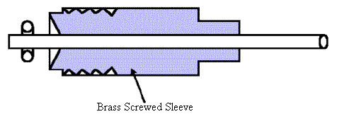
Push the tube through the brass sleeve. Leave approximately 1cm
sticking through. Carefully enter the sleeve and tube into the cell and screw clockwise
using your fingers.
Once finger tight use the spanner to tighten further by1/4 turn. DO
NOT OVERTIGHTEN.
To change the small ‘O’ ring, you will find a small tool in
your kit.
Very gently screw the tool into the ‘O’ring and remove it.
To replace the ‘O’ ring fit the new one onto the tube and
proceed at 3) above.
FILLING THE CELL WITH SAMPLES
- Remove the plastic ring at the front of the cell
- Loosed the pressure screw.
- Remove the window carrier being careful not to drop the window.
- Slide the piston back into the cell by about 3mm.
- Fill the cavity with the sample .
- Replace the window carrier. Gently tighten the screws.
- Push the piston into the oven assembly to slightly compress the sample against the
window.
- Tighten the pressure screw very gently.
- Replace the plastic ring at the front of the cell.
EMPTYING THE CELL WITH SOLID SAMPLES
Repeat the above procedure.
Push the sample out of the cell before point 3) above.
REPLACING THE 'O' RINGS IN THE OVEN
AND FITTING THE CONVENTIONAL
HOT CELL ACCESSORY
- Remove the front window carrier, window, pressure screw, spacer and piston.
- Carefully put these in the camera case in a plastic bag ready for future use.
- Push the conventional hot cell accessory into the cell.
- The stainless steel tube in the centre will slide out. It may release the
‘O’ ring at the rear of the cell.
- Remove the accessory and pull out the front ‘O’ ring.
- Store ready for reuse in the camera case.
- Slide the accessory into the cell. Fit 2 screws and tighten gently.
FILLING THE CONVENTIONAL HOT CELL
ACCESSORY WITH SOLID SAMPLES
- Withdraw the piston by about 3mm.
- Fill the cavity with solid.
- Place the pressure pad over the open end.
- Push the piston towards the to compress the sample.
REMOVING THE CONVENTIONAL HOT CELL
ACCESSORY & REBUILDING THE SEALED CELL
- Remove the conventional hot cell accessory
- Fit the piston into the pressure screw.
- Fit the piston ‘O’ ring. * If the rear 'O' ring has come out of the cell then
fit the 'O' ring to the stainless steel tube.
- Fit the spacer, then the stainless steel tube and slide the complete unit into the cell.
- Screw in the pressure screw until it is finger tight.

- Fit the front ‘O ‘ ring into its groove.
- Press the pressure pad firmly over the open end of the cell to seat the
‘O’ring.
The cell is now assembled ready for filling with sample.
DO NOT ATTEMPT TO DISMANTLE THE LID OF THE CELL.
The heaters and thermocouple are not customer repairable. If the cell
becomes dirty or contaminated with use, or an electrical fault develops please contact
Ventacon. The cell will need to be returned to us.
Hot Cells
[Home] [Who is Ventacon] [Raman Products]
[NIR Products] [Contact Us] [Links]
© Ventacon 2007 |


